- All Products
- Shop by Brands
- BW Technologies
- BW Technologies
- BW Technologies Monitors
- Models
- BW Clip
- BW Clip4
- GasAlertClip Extreme
- GasAlert Extreme
- GasAlertMicroClip XT
- GasAlertMicroClip XL
- GasAlertMicroClip X3
- GasAlertQuattro
- GasAlertMax XT II
- GasAlertMicro 5 Series
- SamplerPak
- IntelliDox Docking System
- MicroDock II
- BW Ultra
- BW Solo
- Gas Monitors
- Gas Monitor Manufacturers
- BW Technologies
- Bacharach
- Biosystems
- Crowcon
- Draeger
- Gas Clip Technologies
- GfG Instruments
- GMI/Detcon
- Honeywell Analytics
- Industrial Scientific
- IGD
- mPower
- MSA
- RAE Instruments
- RKI Instruments
- WatchGas
- Gas Monitor Categories
- Single-Gas Monitors
- Multi-Gas Monitors
- Zero Maintenance Monitors
- Fixed System Gas Monitors
- Confined Space Kits
- Wireless Fixed Point Gas Detectors
- Hydrogen Sulfide (H2S) Monitors
- Calibration Gas
- Combustion Analyzers
- Water Quality
- Reliability Instruments
- Refractometers
- HVAC
- Weather
- Temperature
- Laboratory
- Sound
- IAQ
- Electrical
- All Categories


Device Configuration
Device Configuration
The Device Configuration section displays data about the detector, allows for a startup message to be entered, and is used to enable/disable and define settings for the detector.
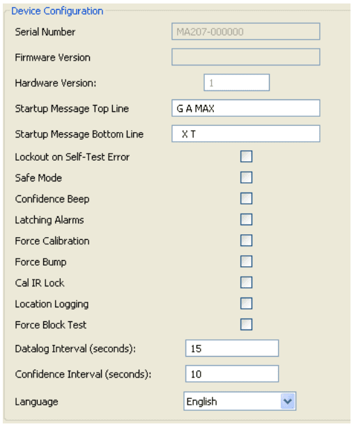
Figure 4. Device Configuration Section
Refer to the following options for descriptions and functionality.
The Serial Number, Firmware Version, and Hardware Version fields require no data entry. Settings for these fields are factory defined.
Serial Number Field
This field displays the serial number (e.g. MA110-001000) of the detector.
Firmware Version
This field displays the current firmware version (e.g. 02_000) that displays on the detector LCD during the startup tests. If new firmware is uploaded to the detector, the Firmware Version field automatically updates.
Hardware Version
This field displays the current version of hardware the detector is operating with.
Startup Message Top Line
Enter a line of text that will display on the detector LCD during startup (maximum 25 characters, spaces included). Enter any type of information such as employee name, plant, area, emergency number(s), etc.
Depending upon the length of the message, text will either display or scroll across the top line of the LCD.
Startup Message Bottom Line
Enter a line of text that will display on the detector LCD during startup (maximum 25 characters, spaces included). Enter any type of information such as employee name, plant, area, emergency number(s), etc.
Depending upon the length of the message, text will either display or scroll across the bottom line of the LCD.
The user options define the settings for the detector.
When options are enabled/disabled, the checkbox displays with a red frame until the new settings are saved to the detector.
Lockout on Self-Test Error (failed sensor lock)
If enabled and a sensor fails during startup, the following screens display and the detector deactivates.


To enter normal operation, the sensor must be operating correctly. Refer to Troubleshooting and Replacing a Sensor or Sensor Filter.
The detector is shipped with the Lockout on Self-Test Error option disabled.
Safe Mode
If enabled, SAFE displays continuously on the LCD unless an alarm condition occurs.

If an alarm condition occurs, the LCD displays the real-time readings for each sensor.
Confidence Beep
If enabled, the confidence beep provides continuous confirmation that the detector is operating correctly. To define how often the detector beeps (every 1-120 seconds), enter the value in the Confidence Interval field.
Confidence beep automatically disables during a low battery alarm.
The detector is shipped with the Confidence Beep option disabled.
Latching Alarms
If enabled, a detector alarm persists until the alarm is acknowledged and
gas concentrations are below the low alarm setpoint. The audible alarm
can be temporarily deactivated by pressing  , but the LCD continues to display the high peak concentration until the alarm condition no longer
exists.
, but the LCD continues to display the high peak concentration until the alarm condition no longer
exists.
The detector is shipped with the Latching Alarms option disabled.
Force Calibration
Force Calibration Enabled: If enabled and a sensor(s) is past due for calibration, the following screen displays.

The sensor(s) must be calibrated to continue and enter normal operation. For complete instructions, refer to Calibration.
If the calibration is unsuccessful for any of the sensors, the detector deactivates.
Force Calibration Disabled: If disabled, the CAL DUE NOW screen
displays. Press to acknowledge the warning and enter normal
operation.
The detector is shipped with the Force Calibration option disabled.
If overdue for calibration, BW recommends the sensor(s) be calibrated immediately.
Force Bump
A bump test must be performed regularly to ensure the sensor(s) are responding correctly to test gas. If enabled and the sensor(s) is past due, a bump test must be performed and the overdue sensor must enter into alarm. If this option is enabled, the following screen displays during the startup tests.

If Force Bump is enabled, enter a value (1-365) in the Bump Interval (days) field located in the Sensor Configuration section.
If 0 is entered in the Bump Interval (days) field, the Force Bump option is automatically disabled.
BW recommends to bump test the sensors before each day