- All Products
- Shop by Brands
- BW Technologies
- BW Technologies
- BW Technologies Monitors
- Models
- BW Clip
- BW Clip4
- GasAlertClip Extreme
- GasAlert Extreme
- GasAlertMicroClip XT
- GasAlertMicroClip XL
- GasAlertMicroClip X3
- GasAlertQuattro
- GasAlertMax XT II
- GasAlertMicro 5 Series
- SamplerPak
- IntelliDox Docking System
- MicroDock II
- BW Ultra
- BW Solo
- Gas Monitors
- Gas Monitor Manufacturers
- BW Technologies
- Bacharach
- Biosystems
- Crowcon
- Draeger
- Gas Clip Technologies
- GfG Instruments
- GMI/Detcon
- Honeywell Analytics
- Industrial Scientific
- IGD
- mPower
- MSA
- RAE Instruments
- RKI Instruments
- WatchGas
- Gas Monitor Categories
- Single-Gas Monitors
- Multi-Gas Monitors
- Zero Maintenance Monitors
- Fixed System Gas Monitors
- Confined Space Kits
- Wireless Fixed Point Gas Detectors
- Hydrogen Sulfide (H2S) Monitors
- Calibration Gas
- Combustion Analyzers
- Water Quality
- Reliability Instruments
- Refractometers
- HVAC
- Weather
- Temperature
- Laboratory
- Sound
- IAQ
- Electrical
- All Categories


Startup Tests
Startup Tests
When the detector is activated, it performs several startup tests. Confirm the following tests occur.
Battery Test
The detector performs a battery test during startup. If the battery has insufficient power to operate, the following screens displays before deactivating.


Recharge the battery for 6 hours and then reactivate the detector. Refer to Charging the Battery.
Audible/Visual Test
1. All of the LCD elements display simultaneously as the detector beeps, flashes, vibrates, and activates the backlight.

Firmware Version
2. The current firmware version installed on the detector displays on the LCD.

Startup Message
3. If enabled and data is entered in Fleet Manager II, a startup message (25 characters per line) displays or scrolls (depending upon length of message) on the LCD. If the startup message option is not enabled, it is bypassed during the startup test.
Refer to Startup Message Top Line in User Options.
Location Logging
4. If the Location Logging option is enabled, the detector prompts for a number (1-999) to be entered that identifies the location (wells, plants, or other areas) where the detector is being used.

Within 3 seconds, press and continue pressing  until
the desired number displays. To scroll rapidly, press and
hold .
until
the desired number displays. To scroll rapidly, press and
hold .
The site ID number that is entered does not reset when the detector is deactivated. If required, enter a new site ID when the detector is again activated.
Pump Test on Startup
The diffusion cover must be attached to the detector to activate the pump and initiate the pump test.
 CAUTION
The maximum hose length for sampling is 75 ft (22m).
5. In cold temperatures, the pump may require a short period of time to warm up before operating. If this is required, the following screen displays.

The LCD displays a countdown of the time remaining (in seconds) for the pump to warm up.
If the Force Block Test option is enabled, the detector performs a pump test. The following screen displays.

Using your finger, block the end of the hose. The following screen displays.

If the hose is not blocked and unblocked within 2.5 minutes, the detector will assume the pump has failed and deactivates.
Successful Pump Test: If the pump test is successful, the following screen displays.

Unsuccessful Block Pump Test: If the pump is not operating correctly, the following screens display before the detector deactivates.

Activate the detector again. If the pump fails the startup again, refer to Troubleshooting.
If the diffusion cover is not attached, the detector beeps and the following screen displays before continuing with the startup tests.

When the diffusion cover is replaced, the detector activates the pump alarm.
HIGH displays, and  and
and  flashes. Press to
acknowledge the alarm and initiate the pump block test.
flashes. Press to
acknowledge the alarm and initiate the pump block test.
Alarm Setpoints
Alarm setpoints vary by region. Refer to Resetting Gas Alarm Setpoints.
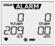
6. If the CO and/or H2S sensor is enabled, the alarm setpoints for the time-weighted average (TWA) and the short-term exposure limit (STEL) display.


Next, the LOW and HIGH alarm setpoints display for all of the enabled sensors.


Self-Test
7. The detector then performs a self-test to ensure it is operating correctly. The following screen displays during the test.

Successful Self-Test: If the self-test is successful, the following screen displays.

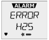
Unsuccessful Self-Test
Lockout on Self-Test Error Option Enabled: If this option is enabled and a sensor fails, the following screens display before the detector deactivates.


If Lockout on Self-Test Error is enabled, the sensor must be replaced to activate and operate the detector. Refer to Replacing a Sensor or Sensor Filter.
Lockout on Self-Test Error Option Disabled: If this option is disabled and a sensor fails the self-test, the LCD displays an error message for the applicable sensor. The startup tests continue.
Enabled sensors are continually tested while the detector is operational.
Automatic Zero for H2S, CO, O2, and LEL
Only activate the detector in a safe area that is free of hazardous gas to ensure an accurate auto zero.
8. To initiate auto zero during startup, the Auto Zero on Startup option must be enabled (sensors are enabled individually).
If the Force Calibration option is enabled and the sensor(s) is past due for calibration, the sensor will not auto zero during startup. The sensor must be calibrated.
If the Auto Zero on Startup option is not enabled in Fleet Manager II for any of the sensors, this startup test is bypassed.
If ambient air is set to be measured as 20.8% vol., the automatic oxygen calibration screen displays 20.8% instead of 20.9%.
If Previous Calibration Failed
If the last calibration performed was unsuccessful, the following screens display.


BW Technologies by Honeywell recommends the sensor(s) be calibrated immediately.
Calibration Due Date (optional)
9. The LCD displays the number of days remaining until the next calibration is due.
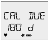
If the Calibration Interval field is set to 0 in Fleet Manager II, it disables the calibration due date function and this test is bypassed. Refer to Calibration Interval in the User Options.
If any sensor is past the calibration due date, the detector beeps, flashes, and vibrates while the LCD displays the following screen.
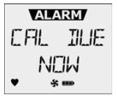
Press to acknowledge the warning. If is not
pressed within 2 minutes, the detector automatically
deactivates.
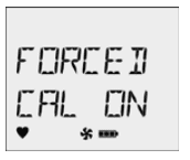
Force Calibration Enabled (optional)
10. If the Force Calibration option is enabled in Fleet Manager II and a sensor is past due, the sensor(s) must be calibrated to continue and enter normal operation.
Press to acknowledge. Refer to Calibration Procedure
to begin calibration. If is not pressed to enter calibration
within 2 minutes, the detector automatically deactivates.
Cal IR Lock Enabled (optional)
11. If the Cal IR Lock option is enabled in Fleet Manager II, the following screen displays.
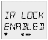
If IR LOCK ENABLED is enabled, the sensor(s) must be calibrated using the IR Link or the MicroDock II station. For more information, refer to Cal IR Lock in User Options.
If Previous Bump Failed
If the last bump test performed was unsuccessful, the following screens display.


BW Technologies by Honeywell recommends the sensor(s) be bump tested immediately.
Bump Test
BW Technologies by Honeywell recommends to bump test the sensors before each day